EQ
|
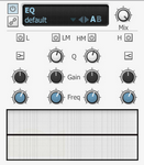
BFD3's EQ provides 4 bands of EQ, including two parametric mid bands. L (Low) and H (High) bands The Low and High bands are switchable between a bell with a fixed Q of 2.5 octave (with the Bell button activated) and a shelving response with a fixed rolloff of 12 dB per octave (with the Bell button deactivated). • Low band Freq range: 40 to 600hz • Low band Gain range: +/- 16.5 dB • High band Freq range: 600 to 14khz • High band Gain range: +/- 20 dB |
LM (Low Mid) and HM (High Mid) parametric bands
The Mid bands feature bell curves with adjustable Q.
• Low Mid Band Freq range: 200hz to 2Khz
• High Mid band Freq range: 800hz to 7khz
• Q range: 0.5 octave to 2.5 octave
Band Power
Each band has its own Power button allowing you to save CPU by only using the bands you need.
SideChain
Enabling the EQ's SideChain button allows you to EQ the channel's sidechain input. It can be very useful to EQ a SideChain input before it enters a compressor as it may feature excessive energy in a part of the frequency spectrum leading to an undesired compression response. Note that the EQ must be placed before the SideChain-enabled processor in the channel's effect chain.
Frequency Display control
The EQ curve can be adjusted by clicking and dragging the graphical display in the EQ effect interface. To edit a band in this way, move the mouse cursor over the display. The display is divided into 4 zones for each band, each highlighted in a different colour corresponding to that of each band's controls on the interface.
With a band highlighted, click and drag up/down to adjust the band's Gain, and left/right to adjust its Freq. For the two Mid bands, click and drag up/down while holding down the ALT key to adjust the band's Q.
EQ8
|
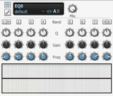
The EQ8 device is an 8-band version of the EQ - it features the same controls but for 8 bands (numbered 1-8) instead of the 4 bands in the standard EQ device. Bands 1 and 8 behave in the same way as the Low and High bands in the standard EQ device, while all other bands behave in the same way as the EQ's parametric Low Mid and High Mid bands. |
Filter
|
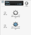
The Filter effect provides non-resonant high-pass and low-pass filters for broad tonal shaping of signals. It can be used to roll off the low end in Overhead and Room buses, or to remove ultra-low frequencies from kick drums, espcially when low-shelving EQ is applied. HP Frequency The -18dB/Oct high-pass filter removes frequencies below the specified frequency which can be set within a range between 20hz and 500hz. LP Frequency The -12 dB/Oct low-pass filter removes frequencies above the specified frequency, which can be set within a range of 35 Hz to 3 kHz. |
Power buttons
The HP In and LP In buttons are power buttons for each filter – when activated, the filter is enabled, and when deactivated, the filter is bypassed.
Filter Mod
|
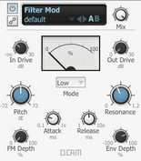
This device features a state-variable multimode filter with a response of 12 db per octave, capable of self-oscillation and featuring input and output drive stages. It has a built-in envelope follower to modulate the filter's cutoff frequency relative to the input's amplitude. This function is modelled on an analogue full-wave rectified envelope follower. Additionally, the filter frequency can be modulated at audio rate by the input signal. Alternatively, the channel's SideChain input can be used as the audio source for the envelope follower and audio-rate FM functions. For example you could use a bass drum tuned very low as a rough and ready LFO to modulate the filter. |
Mode
4 filter Mode settings are available, each offering different filtering functions relative to the cutoff frequency.
Low (Low-pass)
Low-pass mode allows through only frequencies below the cutoff frequency.
High (High-pass)
High-pass mode allows through only frequencies above the cutoff frequency.
Band (Band-pass)
Band-pass mode allows through only a band of frequencies around the cutoff frequency.
Notch
This is the opposite of a band pass - it allows through all other frequencies except a band of frequencies around the cutoff frequency.
Modulating a notch filter can give phaser-like results.
In Drive
The In Drive control sets the amount of signal gain before the filtering stage. As well as increasing the gain, using more drive results in a rich and complex interaction with the filter's resonance due to modelled non-linearities within it.
Out Drive
The Out Drive control adjusts the gain of an OTA-type non-linear amp function at the output, in order to boost and colour the filtered signal.
Pitch
The Pitch control adjusts the cutoff frequency of the filter. It is measured in semitones.
Resonance
This control adjusts the resonance of the filter, accentuating the frequencies around the cutoff frequency set by the Pitch control.
High Resonance settings cause the filter to self-oscillate – please exercise caution with your speaker levels when using resonant self-oscillation.
Attack
This control changes how quickly the envelope follower section responds to transients in the input signal. Longer Attack times mean that the filter takes a longer time to respond to amplitude changes.
Release
The Release control changes how quickly the envelope follower causes the filter to return to its original position when the input signal decreases after a transient.
Env Depth
The Env Depth control adjusts the amount of modulation of the filter's cutoff frequency by the built-in envelope follower.
FM Depth
The FM Depth control sets the amount of audio-rate modulation of the cutoff frequency by the input.
SideChain
Enabling the SideChain button results in the channel's SideChain input being used as the source for the FilterMod device's envelope follower and audio-rate FM features. This means other channels can be used to modulate the filter cutoff.
This function allows you to be very creative with the filter – here's a few ideas to try out:
•for quick and dirty LFOs, try tuning a kick down really low and using it as the filter FM source, perhaps after some additional processing such as low-pass filtering
•load arbitrary sounds as user samples using BFD3's sample import functions, and use them as the filter FM source
•try using the TestTone or TestPulse devices as filter FM sources
Comb
|
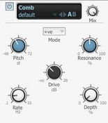
The Comb device is useful for psychedelic chorus and phaser-style effects. Comb filters use technique of feeding a delayed version of the signal back into itself to create a series of harmonically related notches across the frequency spectrum reminiscent of the teeth of a comb. Changing the amount of delay affects the position of these notches and creates the effect of 'sweeping' the resultant frequency bands. Pitch The Pitch control adjusts the centre frequency of the comb filter, changing the position of the comb frequency bands. Resonance The Resonance control adjusts the amount of feedback used for the comb filter. |
Mode
The Mode control sets the feedback polarity between positive and negative settings.
Drive
The Drive control increases the level of the signal entering the comb filter circuit, adding saturation and overdrive.
Rate
The Rate control adjusts the speed of the Comb device's built-in sine LFO for modulating the Pitch.
Depth
The Depth control adjusts the amount of modulation of the Pitch control with the internal sine LFO.
HiLo Balance
|
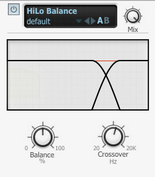
The HiLo Balance device is a 'tilt'-style EQ which cuts high frequencies when boosting low frequencies, and vice versa. Balance The Balance control sets the degree of 'tilt' between low and high frequencies. At the centre position no effect is applied to the incoming audio. At values higher than the centre position, high frequencies are boosted while low frequencies are attenuated by the same amount. At values lower than the centre position, low frequencies are boosted while high frequencies are attenuated by the same amount. Crossover This control sets the point between the low and high frequency bands. |
