Flanger
|
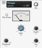
The Flanger effect is a short modulated delay line with feedback to the input. It is used for a sense of movement and for psychedelic effects from the subtle to the extreme. It features a built-in sine LFO for modulating the flanging delay line. Rate The Rate control affects the speed of modulation of the flanger delay time. Depth The Depth control adjusts the amount of modulation of the delay time. Display The VU-style display represents the current flanging delay time. |
Pos (Position)
This control introduces an additional fixed delay time to the Flanger's delay line. It is a very short delay, ranging from 0 ms to 15 ms.
Feedback
This control adjusts the amount of the flanged signal that is fed back into the input.
Higher Feedback settings result in a more pronounced flanging effect. Settings over 50% lead to extreme comb filter type effects.
Spread (stereo only)
This control allows you to adjust the panning of the left and right channel processed signals.
Phase (stereo only)
The Phase control offsets the phase of the internal LFOs for the left and right channels.
Flip Phase
By default (with the Flip Phase button deactivated), the flanged signal is in positive phase with the input signal.
Activating the Flip Phase button inverts the flanged signal's phase in relation to the input signal.
A positive phase setting tends to lead to a more obvious flanging effect.
Phaser
|
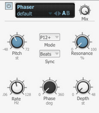
The Phaser uses phase cancelling techniques (with the use of all-pass filtering) to create a series of peaks across the frequency spectrum. When these peaks are swept, a psychedelic sweeping effect is created. Mode The Mode control selects between a number of phaser responses. 4, 6, 8 and 12 stage phaser types are available, with positive or negative feedback. The number of stages refers to the number of all-pass filters within the algorithm. Pitch The Pitch control adjusts the centre frequency of the all-pass filters used in the Phaser algorithm. |
Resonance
The Resonance control adjusts the amount of resonance (feedback) in the all-pass filters.
Phase
The Phase control adjusts the phase between the dry signal and the all-pass filtered signal.
Depth
The Depth control adjusts the amount of Pitch modulation from the Phaser device's internal LFO that modulates the Pitch parameter for classic phaser effect sounds.
Rate
The Rate control adjusts the speed of the internal LFO.
Sync
When the Sync parameter is set to BPM, the Rate control is set in tempo-based values relative to BFD3's current tempo. Possible values range from 64th note to 2 bars, including dotted and triplet variations.
In Seconds mode, the Rate control is set as an absolute time value, ranging from 31ms to 4 seconds.
Chorus
|
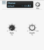
The Chorus effect is a modulation effect that is pitch-based. It is used for thickening up sounds. Rate The Rate control adjusts the speed of pitch modulation. Depth The Depth control adjusts the amount of modulation away from the input signal's original pitch. Spread (stereo only) This control varies the panning of the left and right pitch-modulated signals. |
Bit Crusher
|
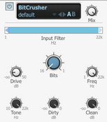
The Bitcrusher effect provides a type of digital distortion that occurs when the sample-rate and bit-depth of the audio is reduced. It allows you to simulate the sound of early samplers, useful for underground hip-hop and other 'lo-fi' styles. Bits The Bits control reduces the bit depth from a maximum of 16 bits to a minimum of 1 bit, which is effectively digital noise. The digital noise generated by the bit-reduction process is referred to as quantisation noise. Early digtal drum machines and samplers tended to have 8 or 12 bit resolution.
|
Freq
The Freq control adjusts the sample rate frequency of the audio processed by the effect and ranges from a maximum of 100 kHz to a minimum of 1 Hz.
Lower sample rates result in an aliasing effect on the processed audio.
Drive
The Drive control adjusts the amount of drive in an OTA-type distortion stage after the crossover filters. This allows gain and colour to be added to the signal before it is processed by the Bit and Freq processes.
Input Filter
This control provides high-pass and low-pass filters for isolating a part of the signal before the sample-rate and bit-depth reduction stages.
To adjust this control, click and drag the light blue arrows at the left and right of the blue active frequency band the light-blue arrows represent the cutoff frequencies of the high-pass and low-pass filters.
These filters are crossover filters – the active frequency band is processed by the bitcrushing circuit with its level adjustable via the Dirty control. The frequencies that are filtered out before the bitcrushing stage are accessible via the Clean control.
Dirty & Clean
The Dirty control sets the amount of processed signal that is heard at the output.
The Clean control sets the amount of the clean signal, which is comprised of the signals filtered out by the Input Filter before processing.
Please note that these are not 'wet' and 'dry' controls – use the Mix control at the top of the effect interface in order to mix between the pre- and post-effect signals.
Tone
The Tone control provides a simple -6 dB/oct low-pass filter for the Dirty signal after the bitcrushing process. It allows you to roll off unwanted high frequencies that may have been generated in the signal as part of the distortion effect.
RingMod
|
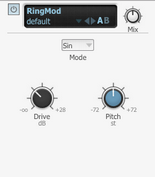
A ring modulator multiplies two signals together, giving you the sum and the difference between them and the output. BFD3's RingMod device contains an internal oscillator that provides one of the signals, the other being the drum sound passing through it. This effect is useful for radical, inharmonic timbral changes for more experimental-sounding mixes. Mode The Mode control adjusts the waveshape of the internal oscillator which is multiplied with the audio input to the effect. Sine, Triangle, Saw, Square and Parabolic oscillator shapes a re available, as well as white or pink noise. |
Pitch
The Pitch control tunes the internal oscillator within a range of an octave.
Drive
The Drive control introduces an adjustable amount of distortion on the input signal. Overdriving the signal in this way changes the waveshape of the input, leading to further variations in the resulting effect.
Frequency shifter
|
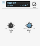
A frequency shifter changes the frequency of the sound passing through it - all frequencies in the signal are adjusted by a fixed amount. This differs from a pitch-shifter which adjusts the frequencies of fundamental frequencies and their harmonics by a proportional amount to preserve the harmonic series of the original signal. Therefore, a frequency shifter usually results in inharmonic and clangorous sounds. Pitch The Pitch control adjusts the amount of frequency shifting, and is represented in semitones. You can shift the input signal's frequencies up or down by up to 36 semitones (3 octaves). Gain The Gain control adjusts the level of the output signal. |
AIR LoFi
|
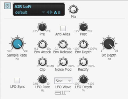
AIR LoFi bit-crushes, downsamples, clips, rectifies, or mangles an input signal. Sample Rate This knob resamples the audio signal at another sample rate. Bit Depth This knob truncates the bit depth of the incoming signal from 16 bits all the way down to 1 bit. Anti-Alias Controls This section controls the anti-aliasing filters that can be used before and after downsampling to reduce aliasing in the resampled audio signal. - Pre: resamples the audio signal at another sample rate. - Post: adjusts the range of anti-aliasing filter cutoff applied to the audio signal after resampling. The filter is applied as a multiplier of the sample frequency (Fs) between 0.12 Fs and 2.00 Fs. - Anti-Alias: For a much grittier sound, disable the Anti-Alias filter. The Anti-Alias button is lit when the filter is enabled. Envelope Modulation Controls This section provides control over an envelope follower that can affect the Sample Rate. This is useful for accentuating and enhancing signal peaks (such as in drum loops) with artificially generated high- frequency aliasing. - Attack: This knob adjusts the time it takes to respond to increases in the audio signal level. - Release: This knob adjusts the time it takes to recover after the signal level falls. Distortion Controls This section provides controls for adding dirt and grunge to the signal. - Clip: Adds transistor-like distortion to the signal. - Noise Mod: Adds a buzzy, noisy edge to the signal. - Rectify: Acts as a waveshaper, adding aggressive, harsh distortion to the signal. LFO Controls The LFO controls apply a low-frequency oscillator (LFO) to modulate the Sample Rate. - LFO Sync: Enable this button to synchronize the LFO Rate to your session tempo. When LFO Sync is disabled, you can set the Rate time in Hertz (Hz) independently of your session tempo. The LFO Sync button is lit when it is enabled. - LFO Rate: When Sync is disabled, the LFO Rate knob lets you change the efefect rate independently of your session tempo. - LFO Wave: Select from the following waveforms for the LFO: LFO Depth This knob adjusts the amount of modulation applied to the Sample Rate.
|
AIR Saturation Filter
|
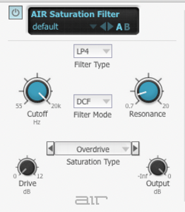
The AIR Saturation Filter applies a filter to an incoming audio signal and then applies a selectable type of distortion, reduction, etc. to that filtered signal. Cutoff This knob adjusts the filter cutoff frequency. Resonance This knob adjusts the resonance at the cutoff frequency. Filter Section These controls determine how the incoming signal is filtered. Filter Type: this selector sets the type of filter: Filter Mode This menu selects the filter’s mode. Select DCF to apply a digitally controlled filter. Select VCF to apply a voltage-controlled filter. Saturation Section This section determines the type and amount of saturation applied to the filtered signal. Saturation Type: this selector sets the type of saturation: Drive: This knob lets you increase the amount of saturation applied to the signal. Sometimes an increase or decrease of just 1 or 2 decibels can make a big difference on the amount and quality of saturation. Output This setting lets you raise or lower the output level of the saturated signal. |
